In your fiber optic cable assembly process, good stripping procedures are unquestionably essential. What happens if the fiber is damaged during the manufacturing process? A small nick or scratch in the optical fiber acts as a time bomb. When the connector is subjected to stress or temperature cycling, this flaw can eventually lead to a crack. (Think about how a diamond blade scrapes glass, weakening it and causing it to crack.) When a cable assembly’s fiber fractures, the connection is degraded or lost. Your cable assembly firm may be forced to repair or replace connectors in the field, which could be extremely costly.
This post contains a number of helpful hints and best-practices.
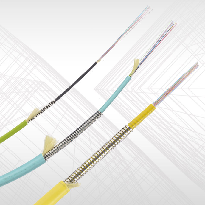
The layers of a typical indoor patch cable are seen in the diagram above. Other types of cables may have different structure or additional layers, but the following is generally true regardless of the number and types of layers involved. Let’s go over some of the most frequent layers and things to keep in mind when stripping.
To begin, keep in mind that when stripping multi-layer cables for connectorization, each layer must often be stripped separately because they all need to be stripped to various lengths. That is, the above cable cannot be stripped in one “go”; the layers must be peeled one at a time. The Jacket, Aramid Yarn, and Buffers must all be stripped. (With the exception of the Buffers, which we’ll discuss further below). As a result, when removing an upper layer, care must be given to avoid damaging the layers beneath. Always make sure to properly maintain your stripping tools, regardless of the ones you use, to keep the cutting blades sharp.
Outer Jacket (1). Sheath is another name for this flexible insulating material, which is usually made of soft plastic.
- OD is normally 2-3mm in diameter on single-fiber cables (as shown above) and can be stripped with standard wire-strippers of the appropriate gauge.
- When choosing the right wire-stripper gauge, keep in mind the layer underlying (in this example, the Aramid Yarn): you don’t want to damage any of the yarn fibers, which are crucial for connection tensile strength for installation purposes.
- After removing the Jacket, observe the Aramid Yarn fibers at the strip point. Are they damaged? Are any of them cut? Even a small % of cut fibers will significantly reduce finished-product pull-strength. If you see cut yarn fibers, likely you need to use a larger gauge wire stripper.
- The edge of the jacket, after stripping, should be cut clean—not torn or ripped.
Aramid Yarns (2). Kevlar® is the brand name for these high-strength members. They give the finished cable assembly tensile strength (they are crimped to the connector body, so that any pull stress applied to the cable after it is connectorized will be taken by the aramid yarn, and not the fiber itself).
- Cutting blades are notoriously dulled by these high-strength synthetic fibers. While any sharp knife, razor blade, or scissors can be used to cut this fabric, they will quickly dull such standard off-the-shelf equipment. Scissors made expressly for cutting Kevlar should be used, as they will last much longer. When they no longer cut easily, they will need to be replaced or re-sharpened.
Secondary Buffer (3a). Is a soft plastic material with a diameter that can vary, but is most usually 0.9um (900um).
- Strip tools made particularly for the diameter buffer you’re trying to strip are necessary for proper stripping. Fiber Strippers is a generic term for these devices.
- To strip these Bufferes, a number of instruments are available, ranging from simple hand tools to heated hand tools (which soften the Buffer tube and make it easier to strip) to completely automated tools. All of them can be used successfully, but automated tools require less operator expertise and are more consistent and repeatable.
- Regardless of the tool used, it is constructed with blade specifications that help ensure the glass fiber below is never contacted by the blade (creating potential damage to the glass fiber).
- The cut edge should be straight and clean, not angled, jagged, or torn in any way (indicating worn-out blades on the stripping tool).
Primary Buffer (3b). A 250um acrylic coating is often applied directly to the glass optical fiber.
- Because this coating is usually bound to the Secondary Buffer to some extent, it is stripped at the same time as the Secondary Buffer. After stripping the Secondary Buffer, the same tool can be used to remove any remaining Primary Buffer from the fiber.
Glass Optical Fiber (4a and 4b). While the Cladding and Buffer zones are two discrete zones within the same fiber, they cannot be separated. Because the Cladding and the Core are both important elements of the Fiber, they can’t be separated.
When utilizing stripping equipment, there are a few things to keep in mind.
Any damage done to the fiber is a ticking time bomb: stress spots where glass cracks can propagate over time, potentially leading to the cable assembly failing suddenly and catastrophically. This is why most Cable Assembly Houses will use some means of analyzing newly-stripped fibers to ensure that no harm was done during the stripping process that was not visible. A popular way is to run a 45-degree bend test on the fiber, which would cause the fiber to break at the scratch spot if the fiber OD had been “nicked” by the stripping tool. While re-stripping the cable would be required, it’s a far better problem to handle than a fiber break in a deployed product.
>> Video: How to strip TiniFiber Stainless Steel Micro-Armor


